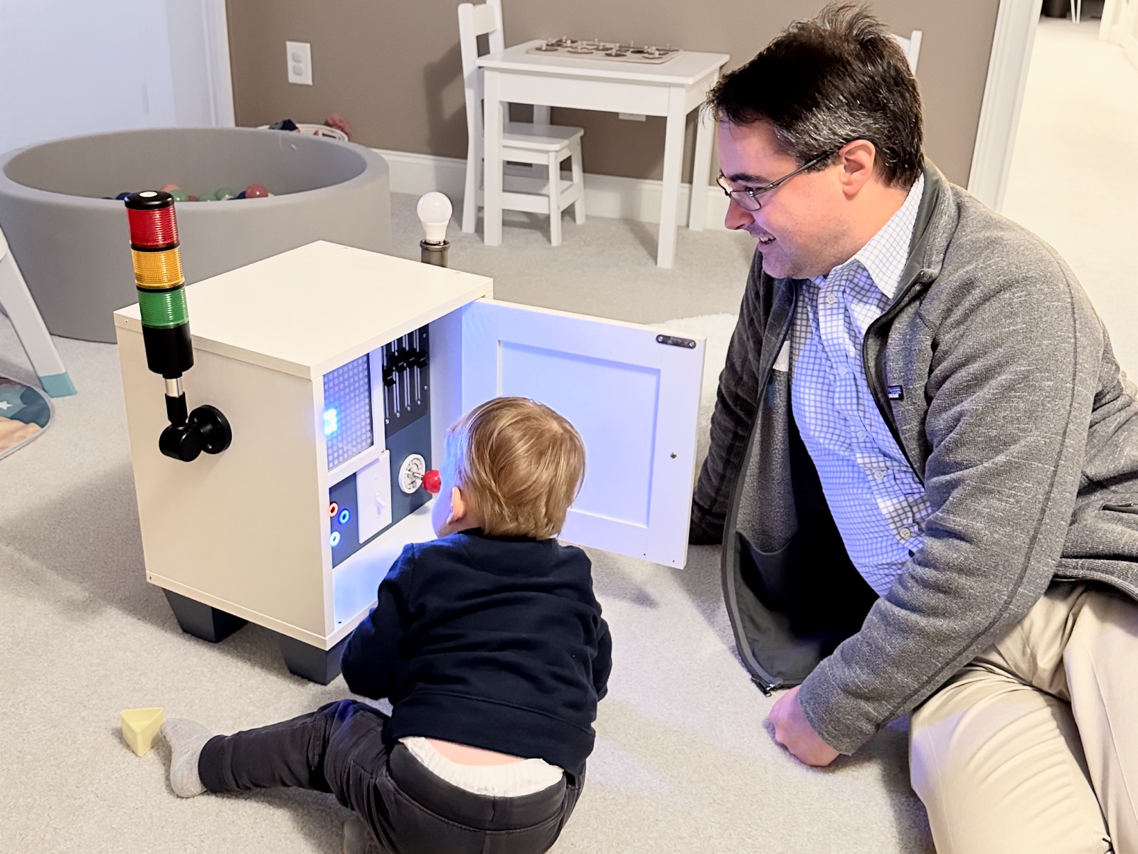
Given the never-ending quest to keep a toddler amused, combined with an evergreen fascination with shiny lights and microcontrollers, I built what I humbly submit as an incredibly over-engineered “busy board.” Leah dubbed it the Wonderbox, and my toddler and his cousins expressed their approval as best they can.
The parts are a smattering of favorite Adafruit products supplemented with random other parts (details below the break). Inputs and outputs are run through an RP2040 microcontroller development board programmed in CircuitPython, so as children get to an age where they might be interested in coding, the Wonderbox could be their first target.
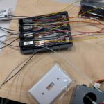
Parts and lead wiring
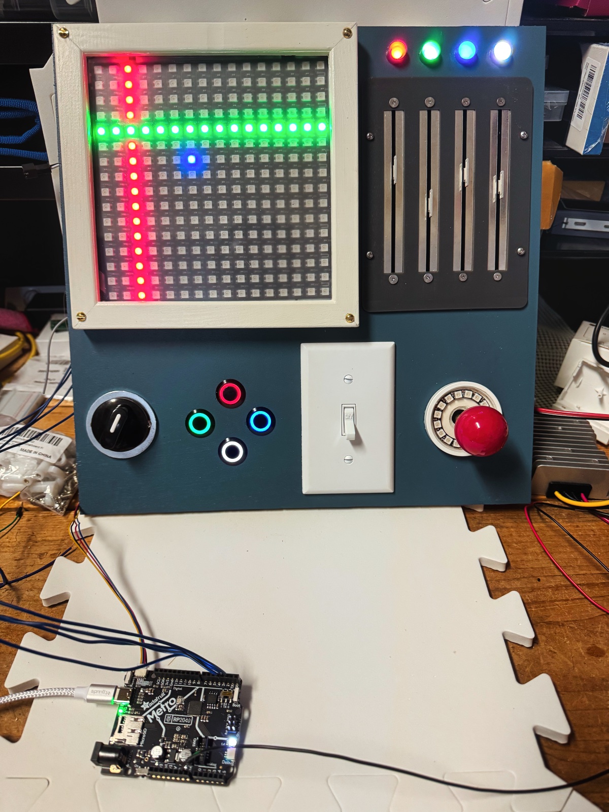
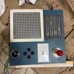
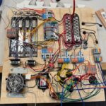
The main “busy board” section of the box consists of:
- a 16×16 grid of addressable LEDs
- four motorized slide potentiometers with conductive nubbins for capacitive touch
- four 8mm addressable LEDs decorating the sliders
- a 4-way rotary switch
- four momentary buttons with incorporated addressable LED light rings
- a standard light switch
- a small arcade joystick
- a 16-pixel individually addressable LED ring around the joystick
To get started, I soldered leads to the LEDs and slider potentiometers (each of which has two motor pins, three potentiometer divider pins, and a capacitive touch pin) and configured an i2c motor controller to run the slider motors.
Building and wiring the board
The idea for this project started with the fact that my toddler, like all toddlers, enjoys slamming cabinets. I found a small surplus cabinet for sale locally, and decided he could slam that. The idea progressed from “he likes lights; I should put a light inside” to this monstrosity.
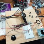
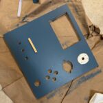
I built the board using hand tools on a piece of finished half-inch plywood cut to the size of the cabinet and painted it with a roller. I prototyped and 3d printed a frame/holder for the four slider potentiometers, and built a frame for the 16×16 pixel grid from angle trim wood. I protected the pixel ring around the joystick with an acrylic circle fitted to a short PVC pipe border.
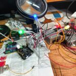
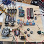
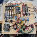
Of course, the real fun began with wiring all of these “busy board” components into a sensible package. Despite picking a microcontroller with lots of GPIO pins, I decided to incorporate GPIO expanders of various sorts to simplify the interface between the busy board and microcontroller — board components all connect on one I2C bus — and to make sure that there are plenty of controller GPIOs free “just in case.”
With that in mind, I added:
- a GPIO expander to handle buttons and switches
- an analog-to-digital converter to process the potentiometer inputs
- a capacitive touch breakout to handle the slider touch pins
- an i2c divider to keep paths short
In a (probably vain) gesture towards reconfigurability, and to distribute power well to potentially high-load addressable LEDs, I made most connections with various lever wire connectors and terminal blocks. I attached PCBs to the wood with M2 standoffs and threaded inserts. The data input to addressable LEDs is directly from the microcontroller to make best use of the RP2040’s built-in PIO state machine. After powering it up, the board worked!
Box, extras, and power management
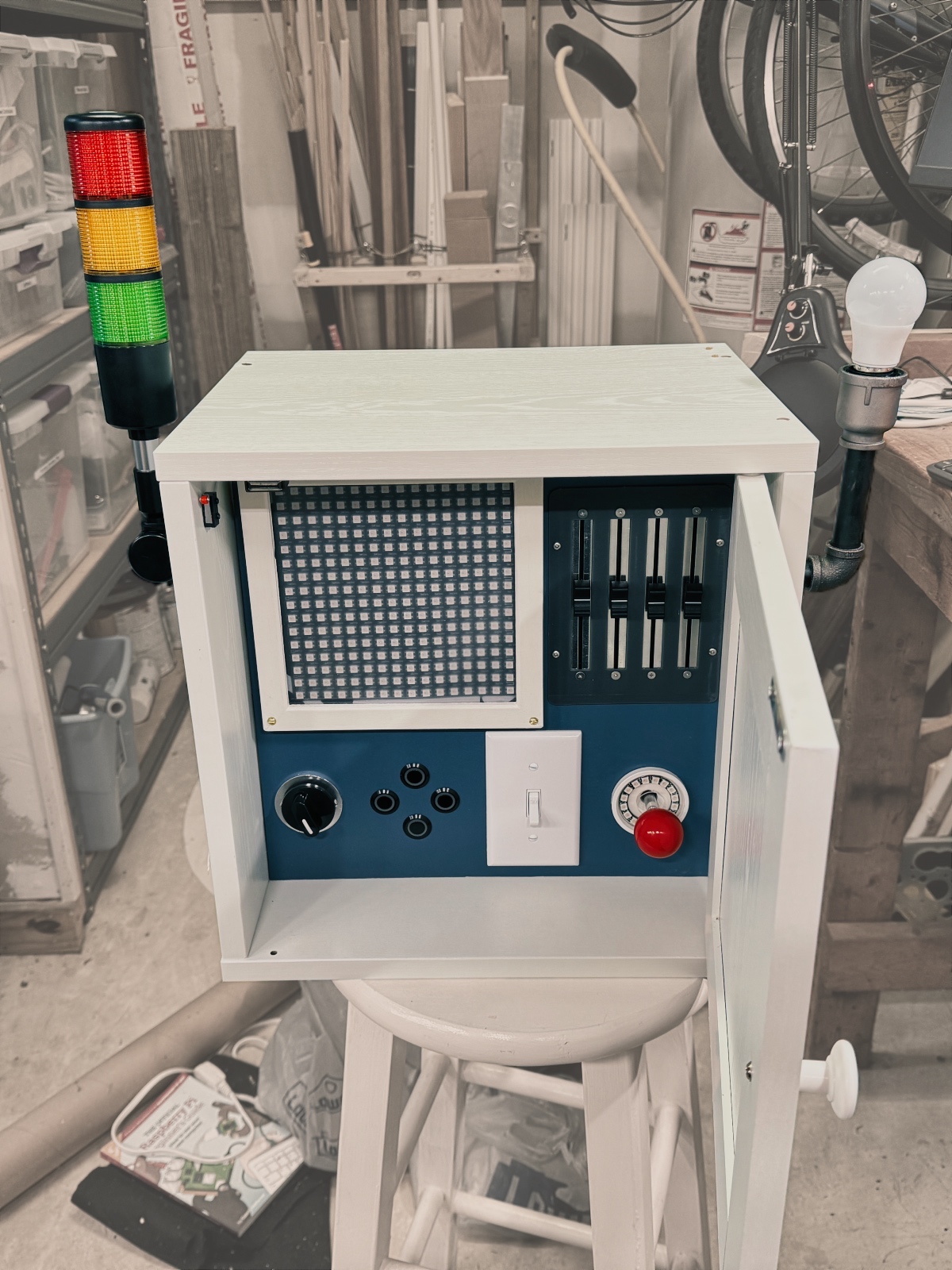
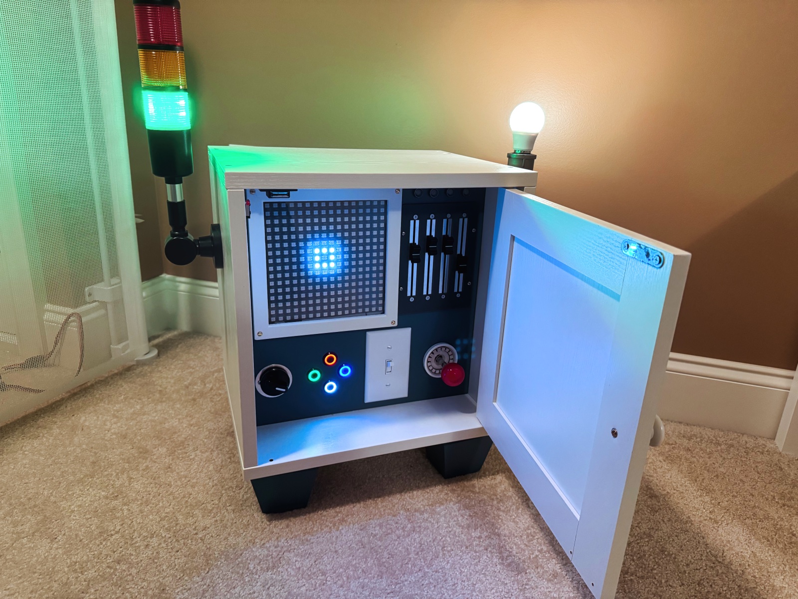
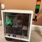
To complete the Wonderbox cabinet, I added a three-color tower light to one side and a 12-volt LED lightbulb connected with pipe fittings to the other. I also added a microswitch to sense cabinet door position.
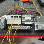
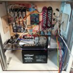
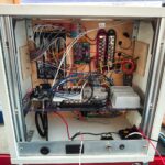
The Wonderbox effectively runs on three voltage levels: the RP2040 is a 3.3V chip; the addressable LEDs and potentiometer motors are 5V, and the tower light and LED lightbulb require 12V. The whole contraption is run from a battery, which I believe is intended for use in an uninterruptible power supply for computers. The 5V and 12V power supplies are converters intended for RV use. 12V power is run to the development board, which contains its own voltage regulators as well. For additional safety, I have a DC circuit breaker attached to the battery.
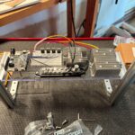
The microcontroller development board and voltage converters are on a piece of polycarbonate that sits over the battery. The final piece there is a small breadboard with N-channel MOSFETs to switch the tower light and lightbulb. Supplying 12 V power through a breadboard isn’t ideal, but these are low current components. I incorporated this into a frame to hold the rear panel as well.
Finally, I finished the rear of the box with a small aluminum panel with a voltage / current meter, panel mount USB connector for easy programming, and a plug for a battery charger. I added a DPDT switch to switch the device on, off, or charge. The remainder of the rear panel is polycarbonate, with a port for ventilation.
Victory
After some basic programming, my toddler and his cousins seem to quite enjoy playing with the Wonderbox. Maybe someday they’ll enjoy programming it, too…

Leave a Reply